

Encountering premature corrosion and leaks in your piping and equipment can be a common challenge – failures or leaks within a system can be found in different sections of a pipeline (e.g. weld joints) which puts the pipeline’s integrity at risk.
Premature failures of an asset can and have raised serious concerns regarding the safety, reliability, and integrity of the facilities, as well as the economic performance of the asset in the short and long terms. It’s important to remember that when conducting analyses for an asset suffering from localised corrosion, there are multiple methodologies and strategies that can be combined to bring you the best results for the health and potential lifespan of your asset.
This insight will take a look at how Penspen conducted a Root Cause Analysis (RCA) on a client’s asset – a SARB Condensate Processing Unit which experienced cracking via corrosion, and what methodologies were combined to combat this problem.
The Fish Bone Diagram
Fish Bone diagrams are generally used as a tool in Root Cause Analyses and serve as a visualisation tool for categorising the potential causes of a problem. Similar to the skeleton of a fish, the diagram is structured with sections or “bones” of the fish labelled as potential causes of the problem at hand. Each bone also branches out into sub-sections, allowing for more detail of the specifics of the causes, and the problem sits at the head. In this instance, the Fish Bone Diagram approach was used as the first step as it is useful in presenting all the possible factors that could influence the cracking and internal corrosion of the asset
The Five Whys Methodology
Another methodology used within Root Cause Analysis is the ‘Five Whys’ – a process that revolves around establishing the reasoning behind the main problem, and four more other reasons as to why that reason came to be. In each stage, the problem or reason is always challenged but is also grounded based on factual information to avoid speculation and the process becoming nothing more than deductive reasoning. This was also implemented to help deduce and focus on the root cause(s) for the corrosion.
Analysis & Results
Based on the analysis, the cracking mechanism in the overhead pipework was considered to be chloride stress corrosion cracking in a sour environment containing H2S, chloride, and water. Through the use of the two methodologies, the Penspen team recognised the root cause of the cracking and corrosion was considered to be a carry-over of chlorides through the process and this carry-over did not appear to have been considered during the design as the material selected was incompatible with the environment. The ‘Five Whys’ methodology helped decipher that the carry-over was linked to neglect in design function when the asset was originally built, and the Fish Bone diagram assisted in the deciphering of the nature of the corrosion (stress corrosion caused by chloride).
Through this, a practicable solution was put forward to avoid the observed cracking and corrosion and the client was also advised on future practices, such as desalting and regular cleaning that would help stop the build-up of deposits within the asset.
Questions? Contact usRelated Insights
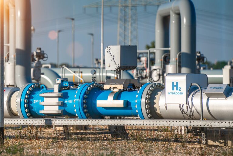
The Pathway Towards Hydrogen Repurposing
In the 30th issue of Dar Magazine, Penspen’s Head of Asset Integrity – East Region, Nick Molnar, explains how historical hydrostatic test data can be used to assess and prioritise pipeline...

Curiosity, Commitment, and Corrosion: Our People – Yureis Villasmil
Passionate about personal development, integrity engineer Yureis shares how her her work contributes to the safe and sustainable delivery of energy throughout Latin America. ...

Development and Implementation of Asset Integrity Management Systems
In the case of facilities, integrity management is somewhat more complex than for pipelines, due to the nature and complexity of these types of assets, which distinguish them from a main...
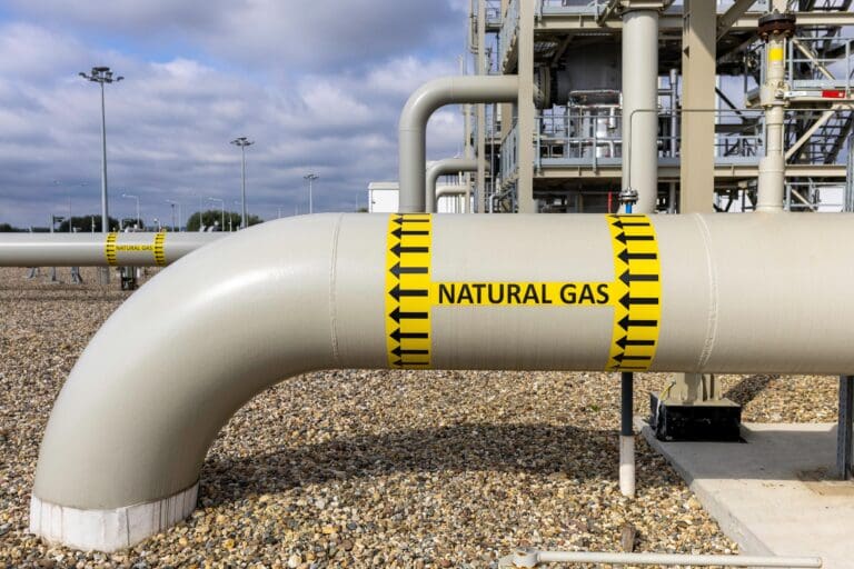
Pipeline Performance vs Dust
In the latest integrity issue of World Pipelines, Penspen Asset Integrity experts explore how dust impacts the integrity, reliability, and safety of gas transmission and distribution systems, and...